Learn how to enable the AI pallet builder and define custom specifications for new pallet designs. This guide walks through the step-by-step process of inputting dimensions and layer details to generate accurate production drawings.
1. The new Pallet Builder tool is a useful feature to develop detailed images of pallets within the system. Assisted by AI, it allows 3D images to be generated which can also be shared during production and with customers.
The tool can be applied when adding a 'new pallet' into the system or when updating an existing 'new pallet' that does not yet have a build list.
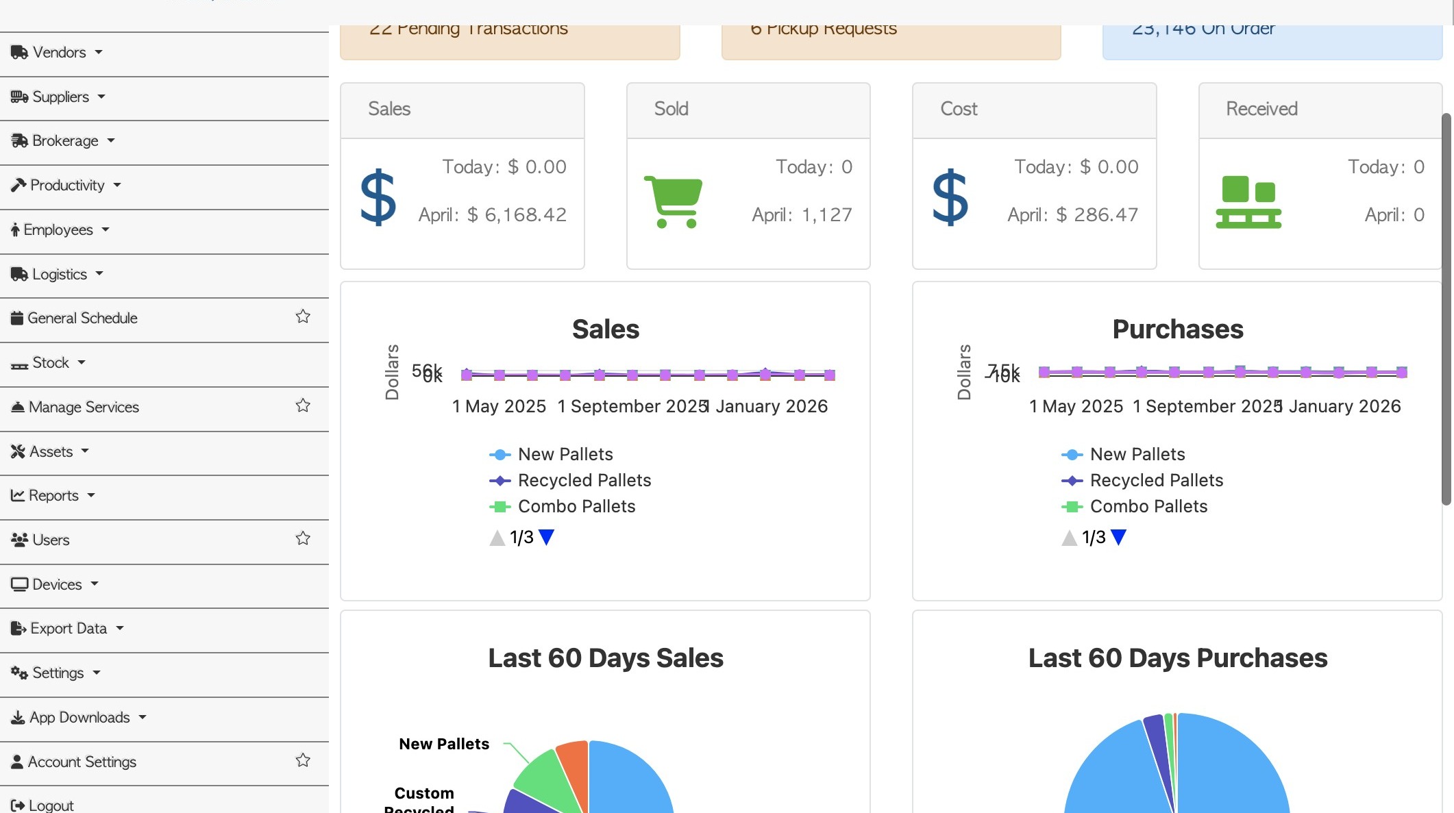
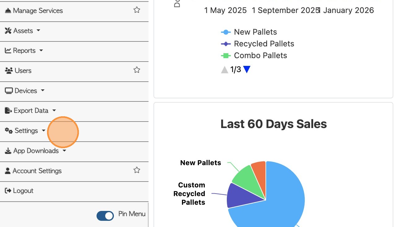
2. #1 ENABLE DRAWING TOOL: From the Main Menu, click "Settings"
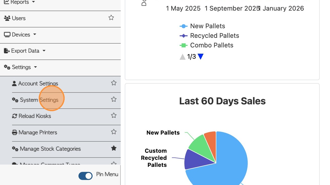
3. Click "System Settings"
4. Click "Ai Config"
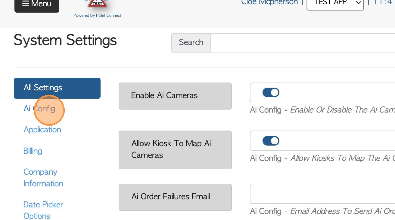
5. Click here to enable "AI 3D Pallet Builder"
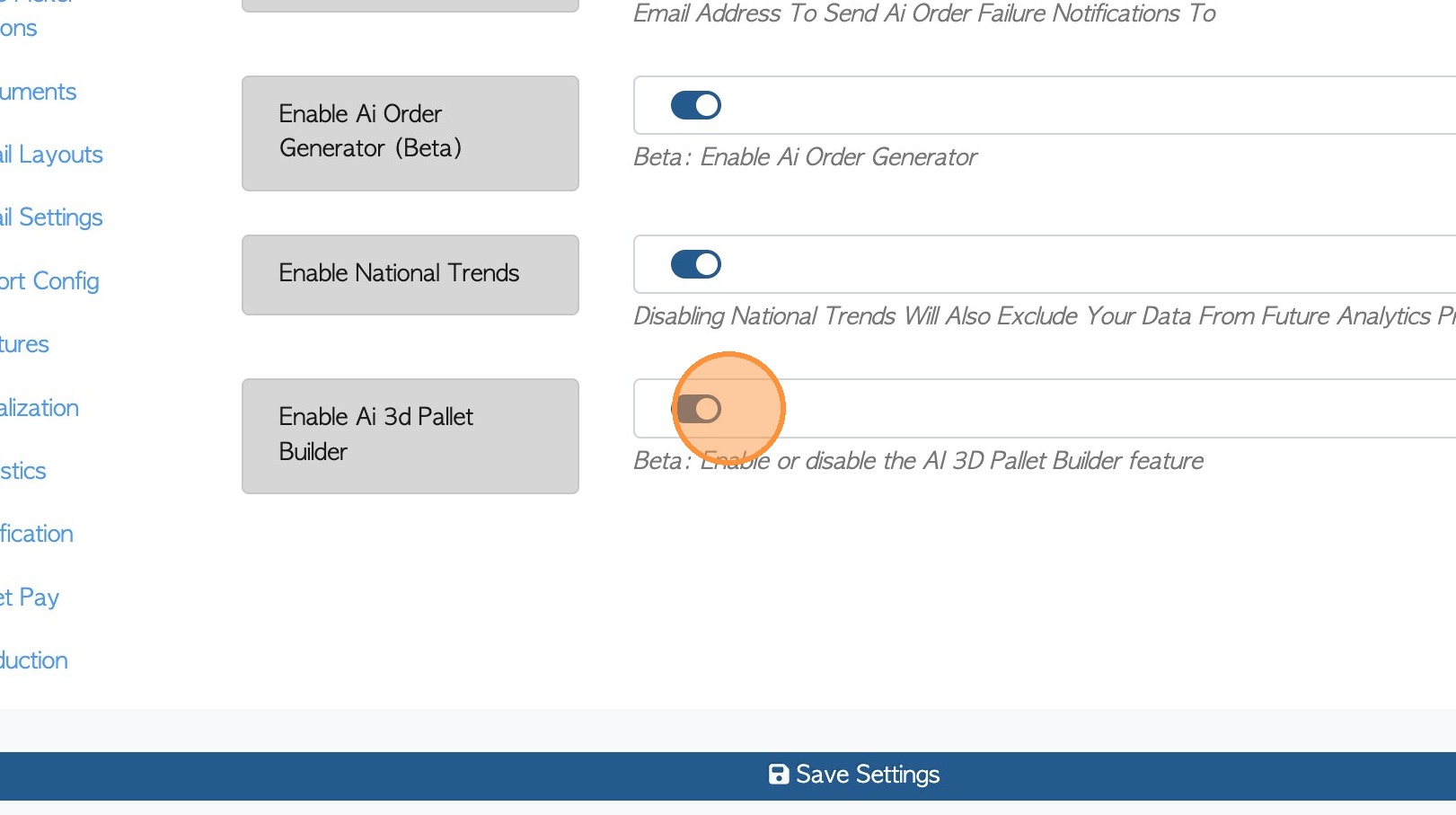
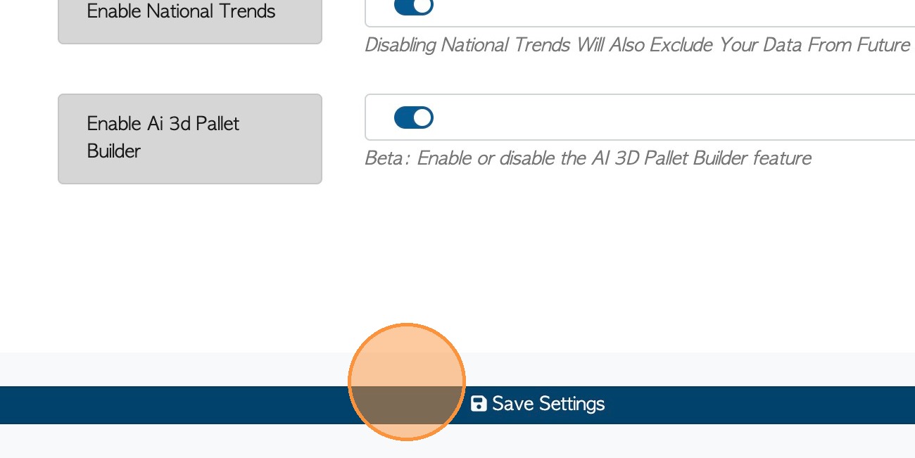
6. Click "Save Settings"
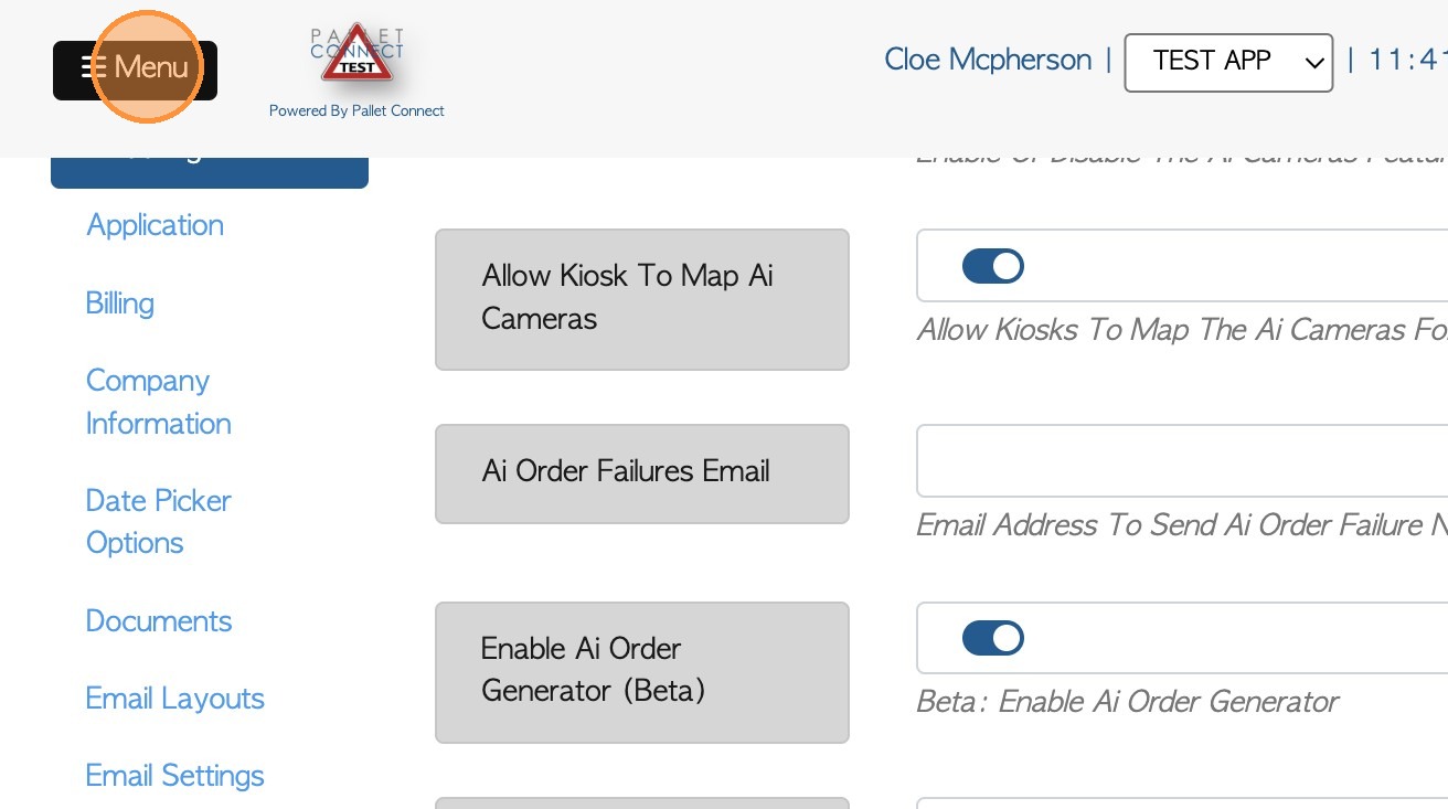
7. #2 UTILIZE DRAWING TOOL: Click "Menu"
8. Click "Stock"
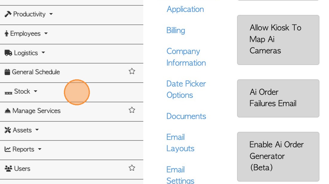
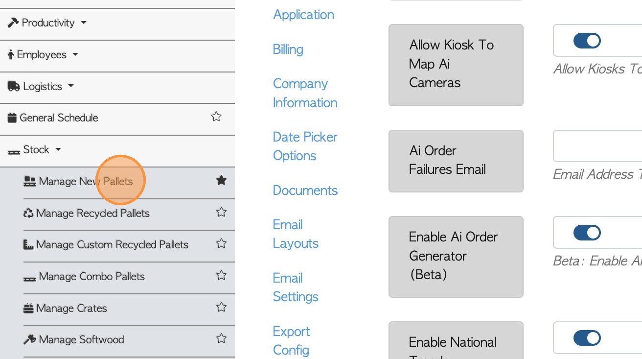
9. Click "Manage New Pallets"
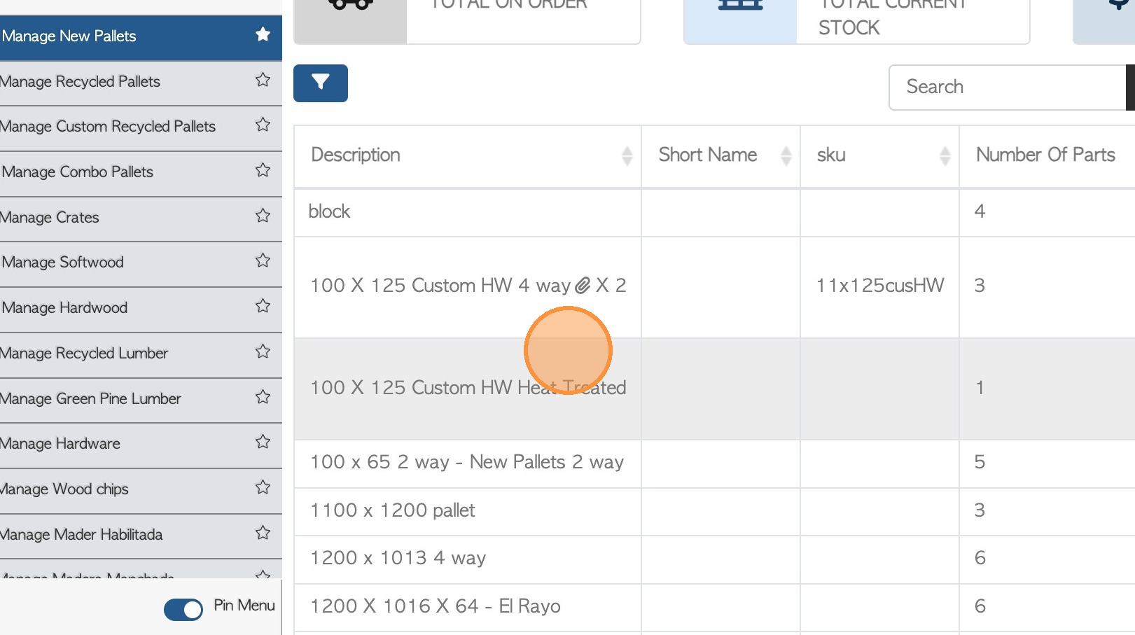
10. Click on the selected stock item from the list.
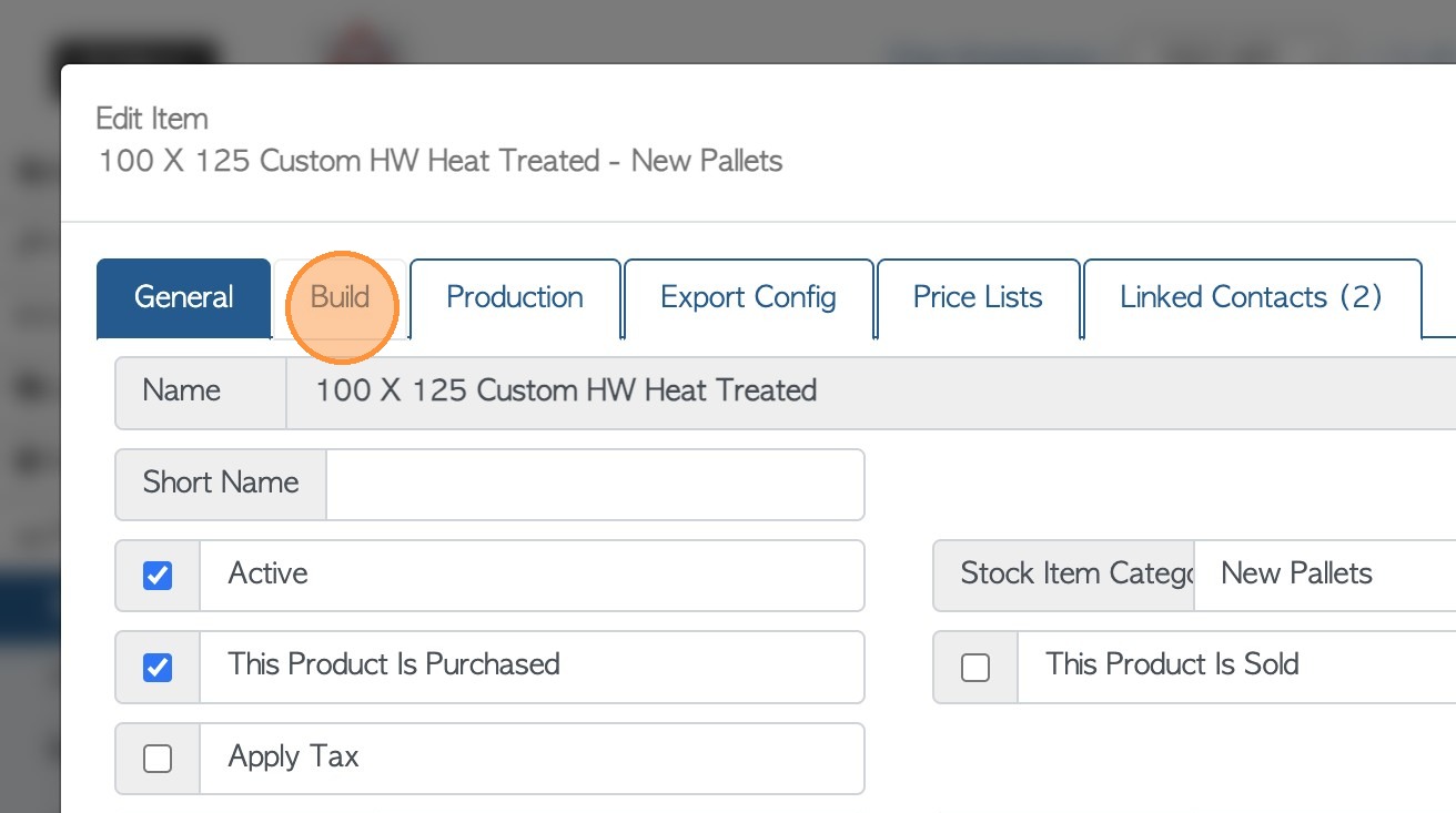
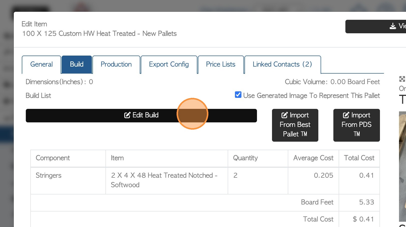
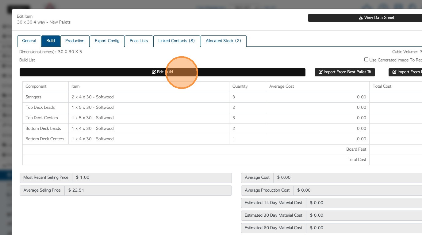
11. Click the "Build" tab.
12. Click "Edit Build" button.
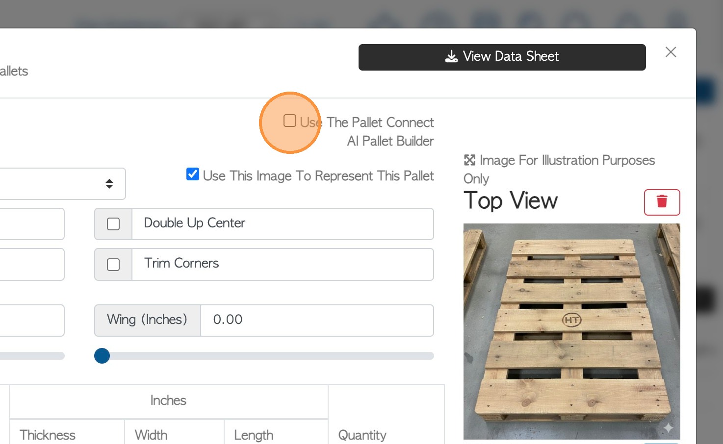
13. Click the "Use The Pallet Connect AI Pallet Builder" field.
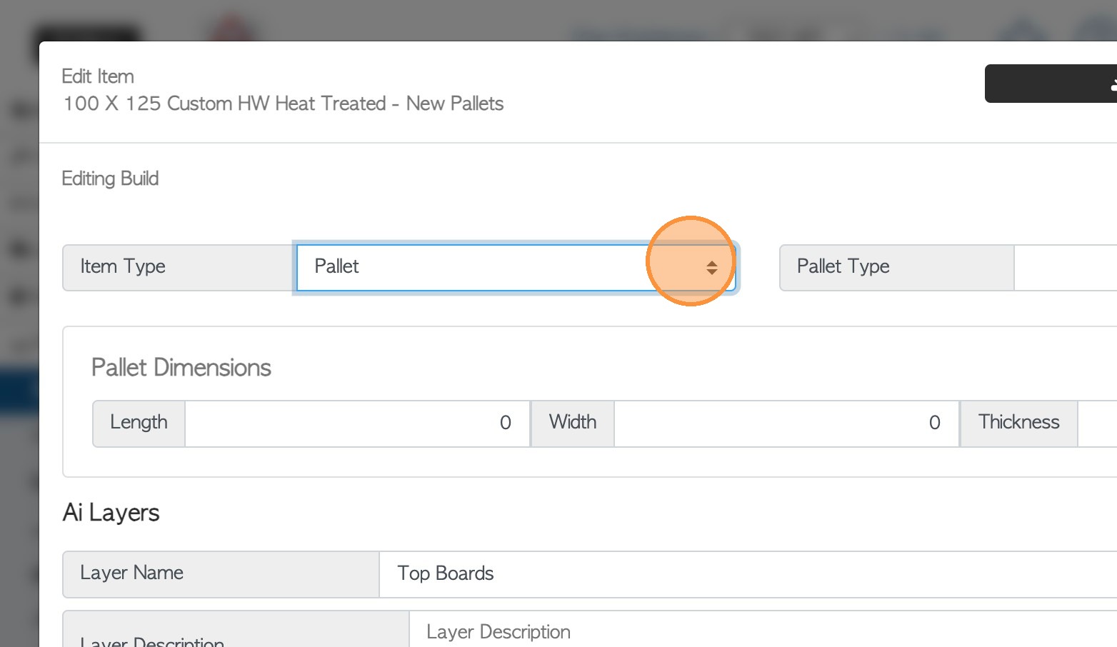
14. Click this dropdown to enter the item type e.g. Pallet.
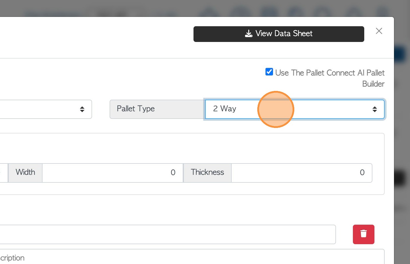
15. Click the dropdown menu to enter the Pallet Type. For example "2 Way", "4 way" or "block".
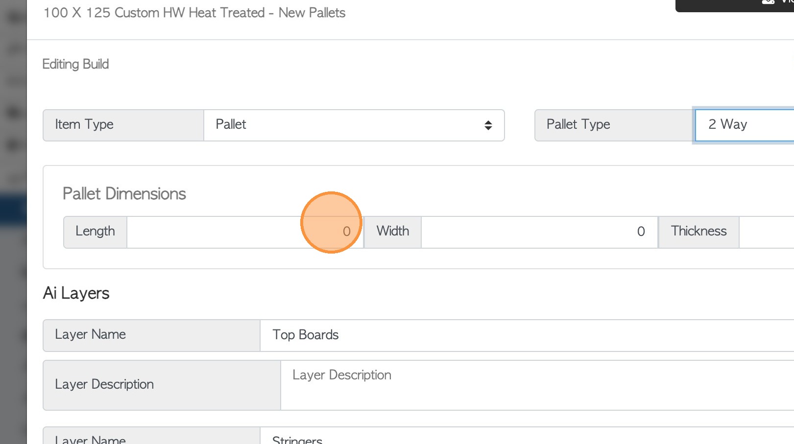
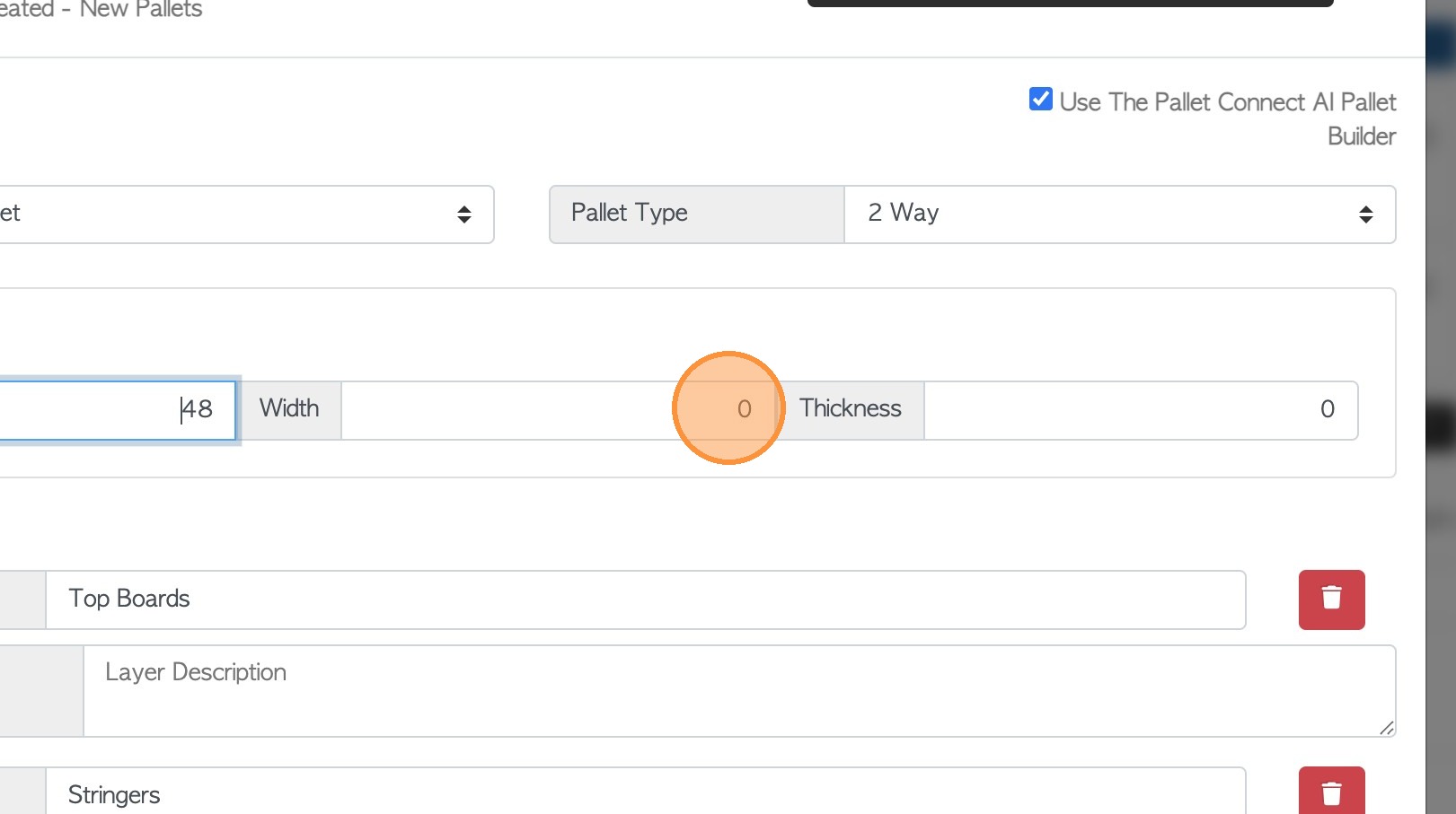
16. Start to enter the pallet dimensions. Click the "Length In Inches" field, to add pallet length.
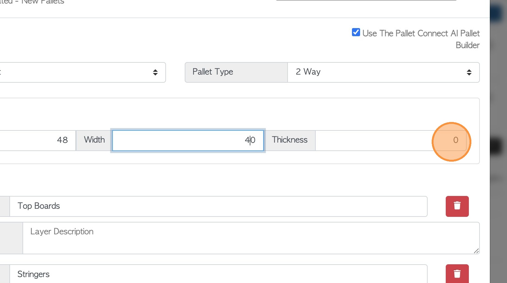
17. Click the "Width In Inches" field to add pallet width.
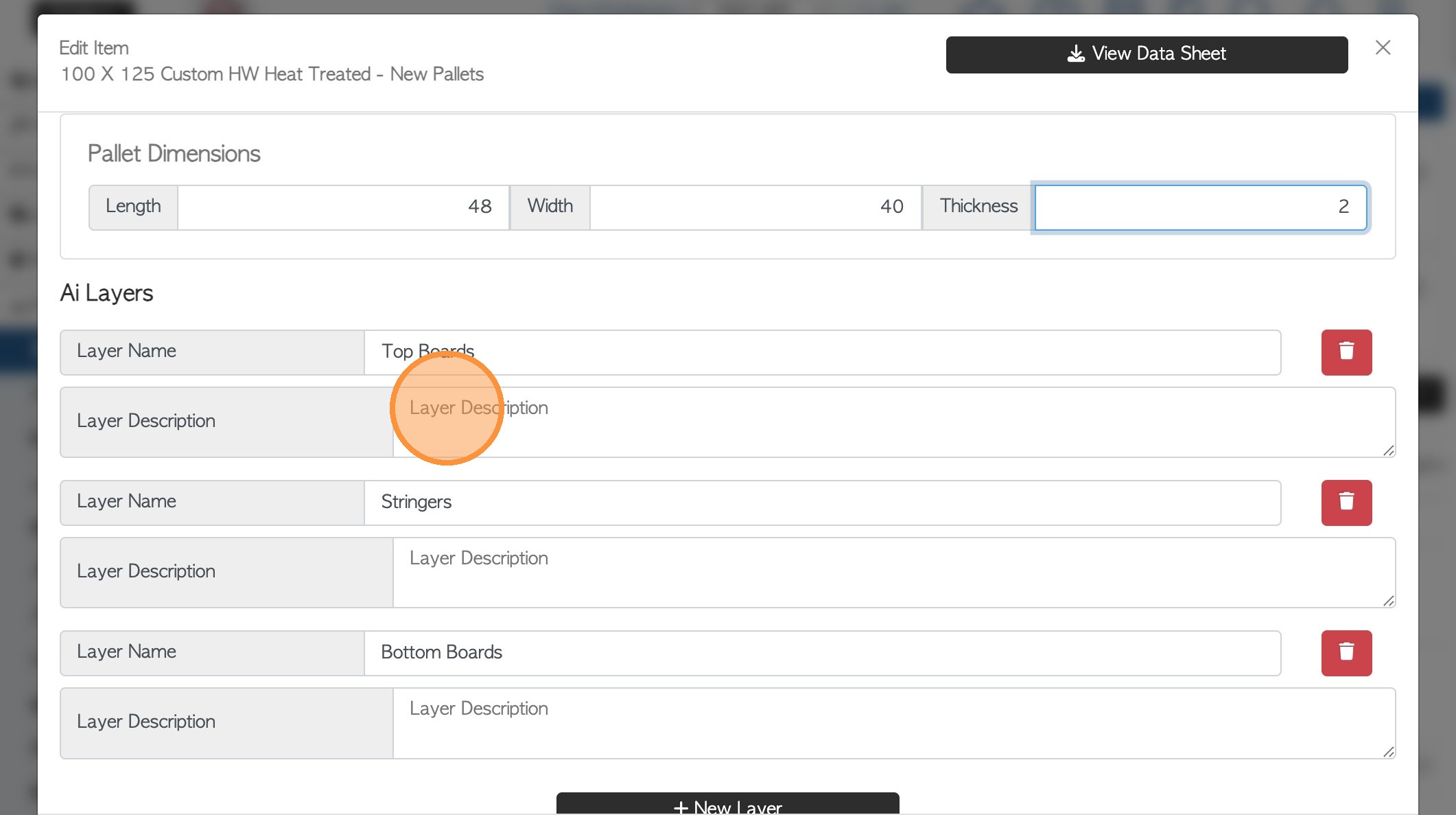
18. Click the "Thickness In Inches" field, to add pallet thickness.
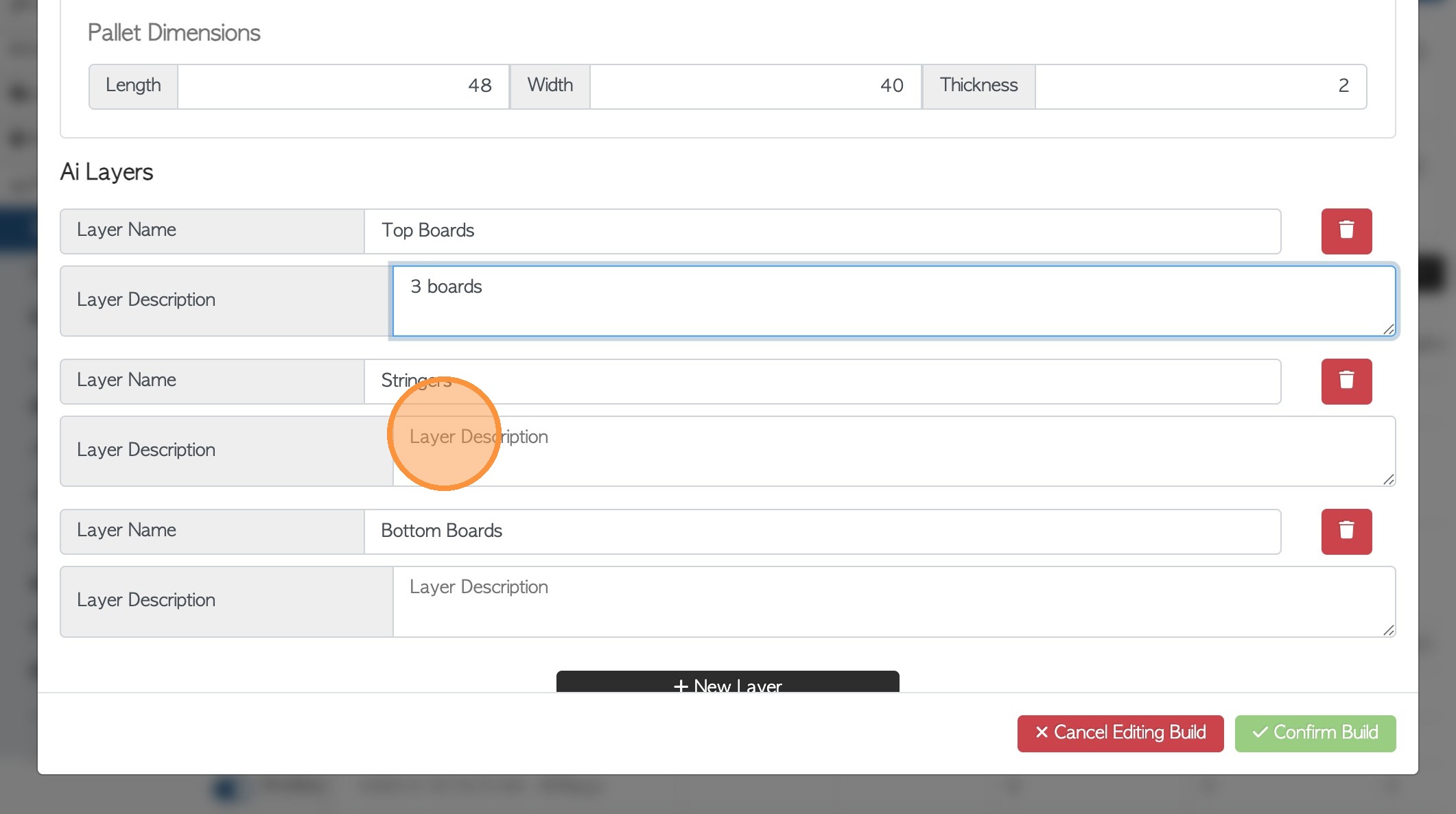
19. Click the "Layer Description" fields to add the details. e.g Top Boards.
Description example: "3 centre top boards and 2 lead boards with a thickness of 1 inch"
NOTE: The Pallet Layers can be removed, added, and changed as needed. There must always be at least ONE layer for the image to generate.
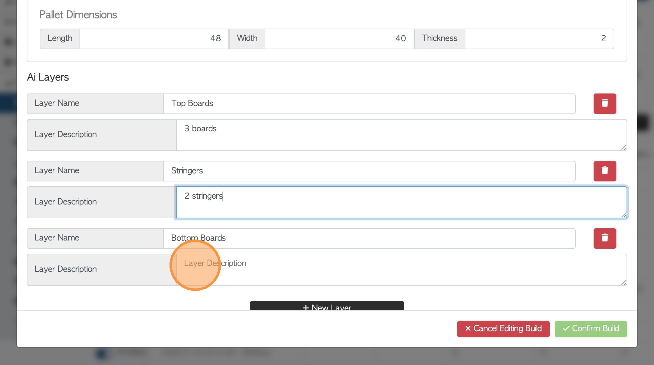
20. Click the next "Layer Description" field e.g. Stringers.
Description example "3 stringers, notched 4 way with a thickness of 4 inches"
21. Click the next "Layer Description" field e.g. bottom boards.
Description example "1 centre board and 2 lead boards with a thickness of 1 inch
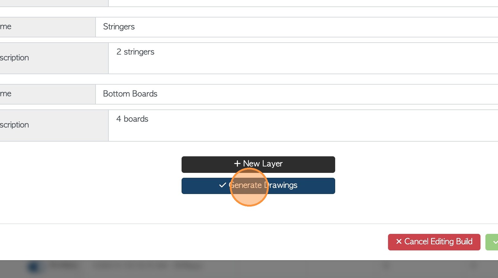
22. Click "New Layer" to add an extra layer, if required.
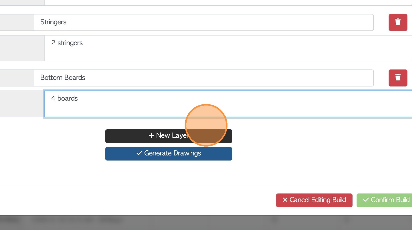
23. If completed click "Generate Drawings".
24. A "Thinking" message will be displayed as the system is generating the image.
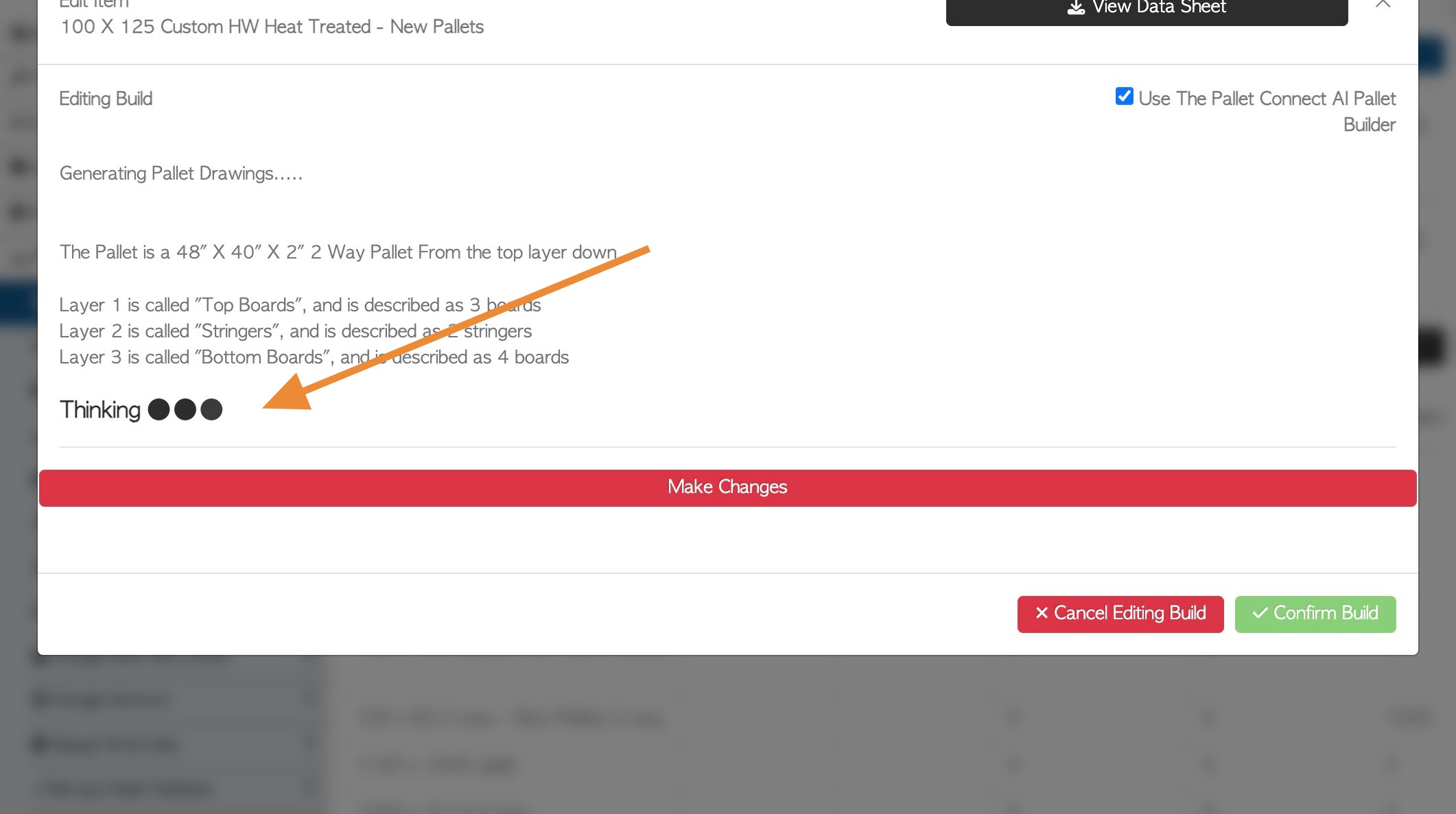
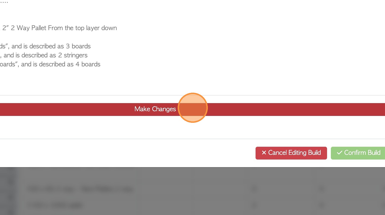
25. Click "Make Changes" to go back and edit the layer information, as needed.
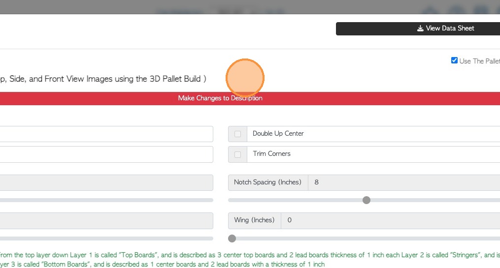
26. Once generated, the details of the pallet will be displayed.
Click "Make Changes to Description" to edit.
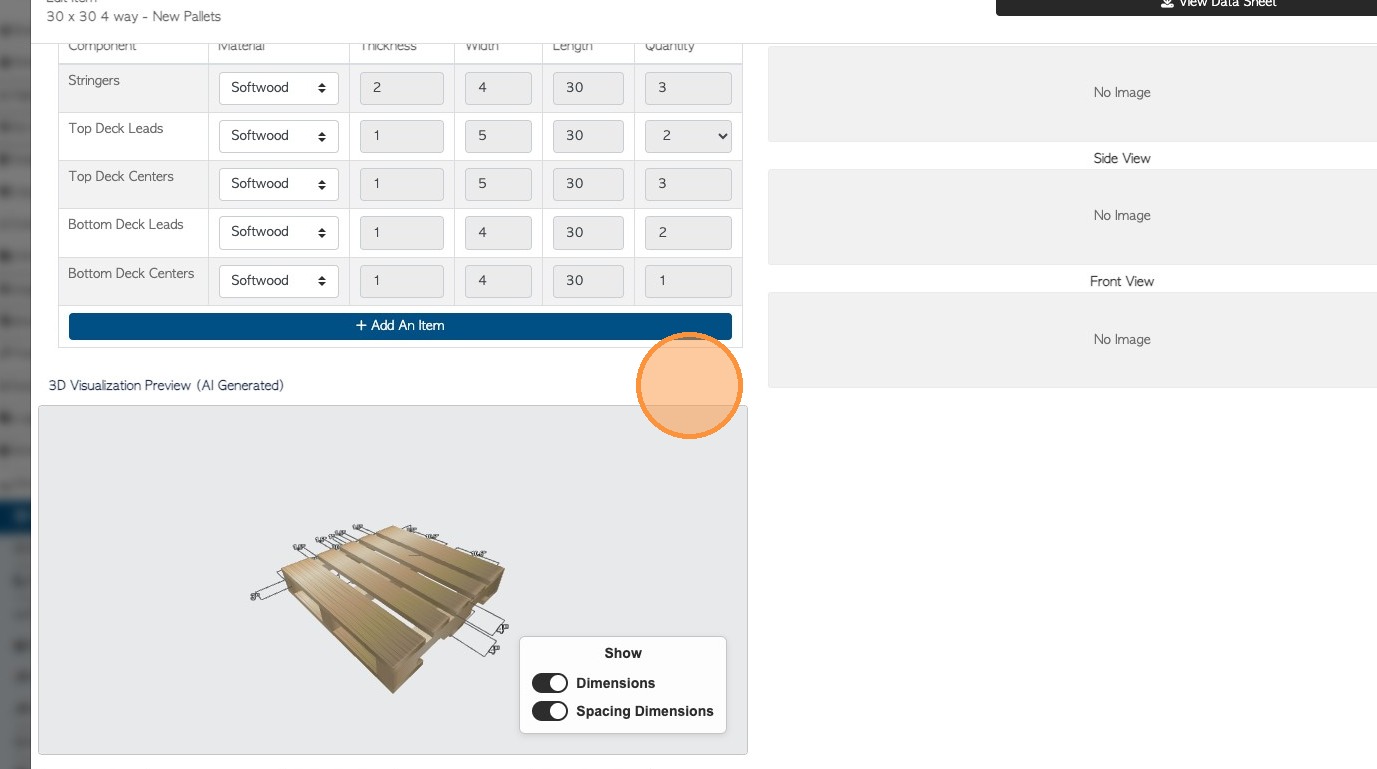
27. A description and a build list are generated.
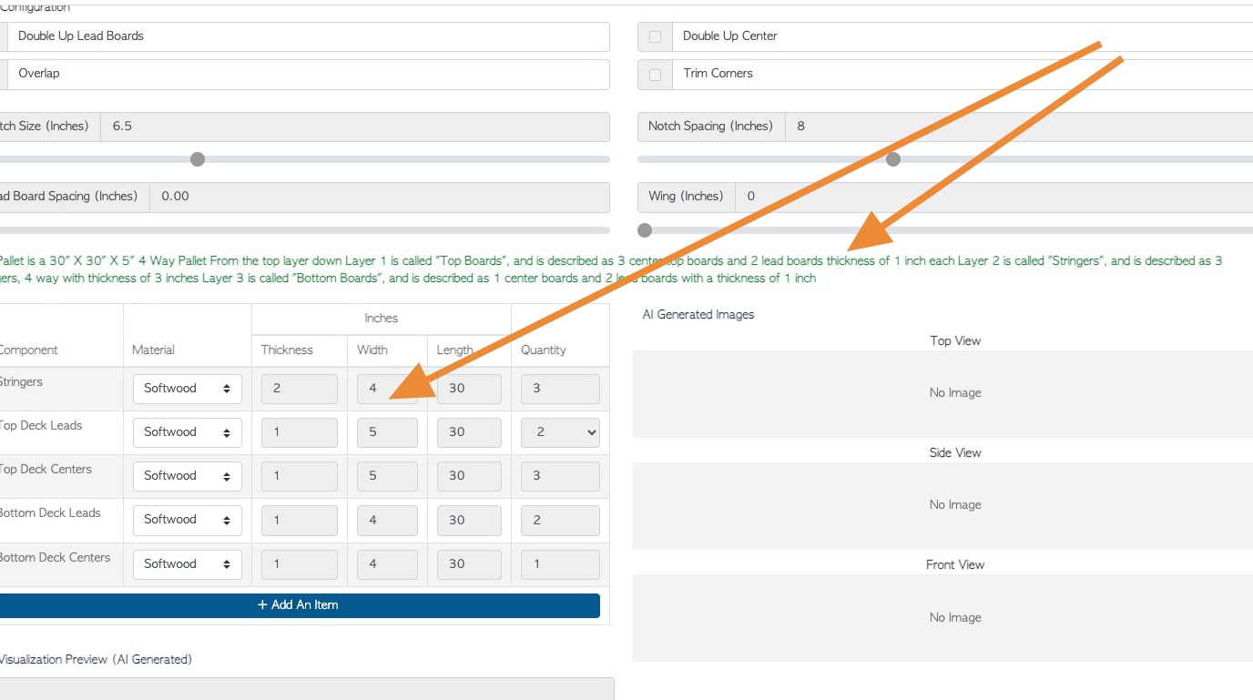
28. A 3D image is generated. Hover over the image with the cursor and zoom in and out of the image and change the angle of the view.
29. Start to add images to the stock item profile.
TIP! To change the view of the pallet, either zoom in/out by scrolling, rotate the camera by holding left click on the mouse, OR move the camera by holding right click.
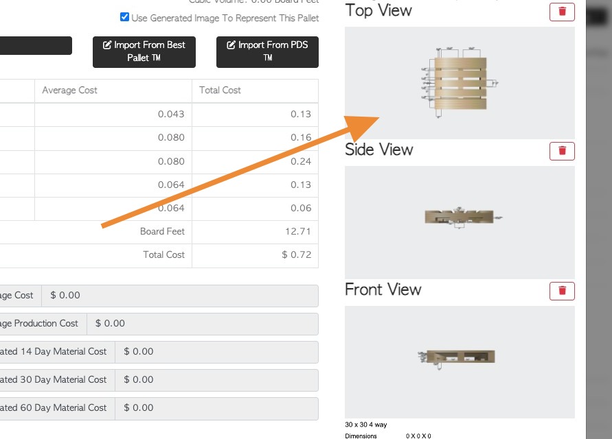
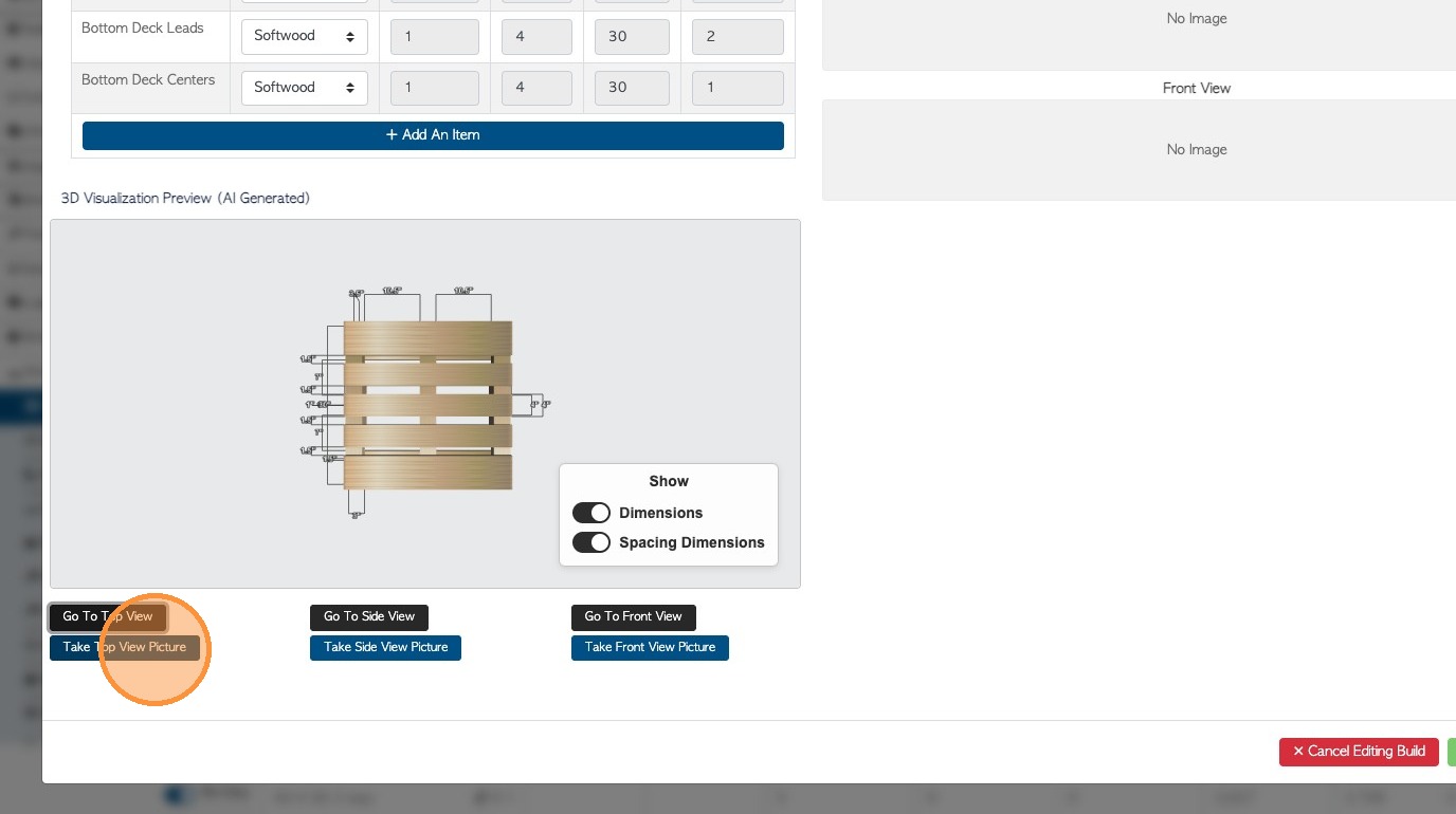
Firstly click "Go To Top View"
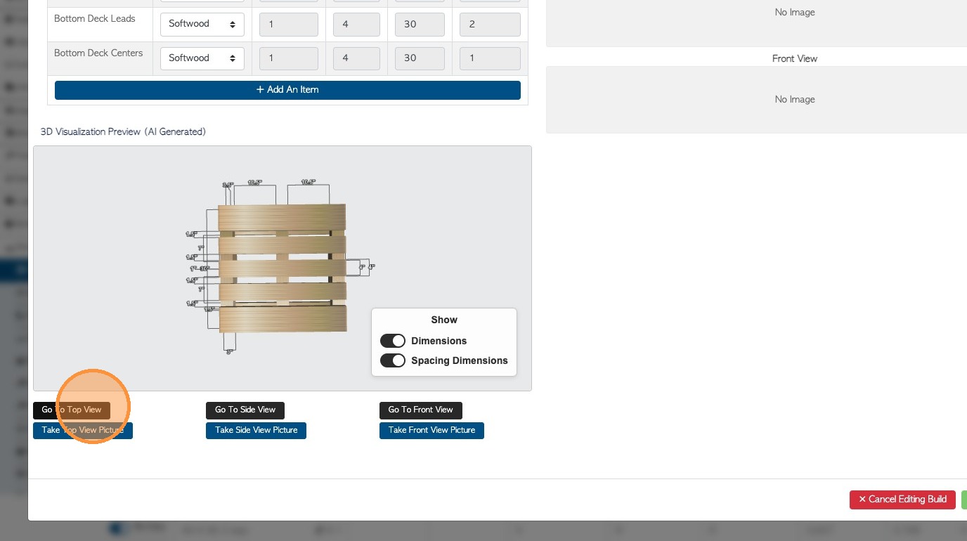
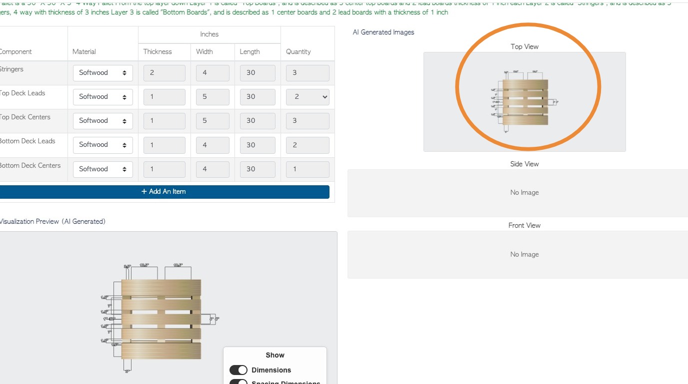
30. Click "Take Top View Picture" to add the image as the top view.
31. This is the image that will be visible in the stock item profile.
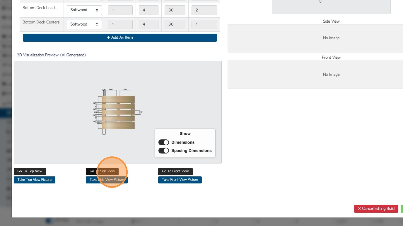
32. Click "Go To Side View" to generate the side view.
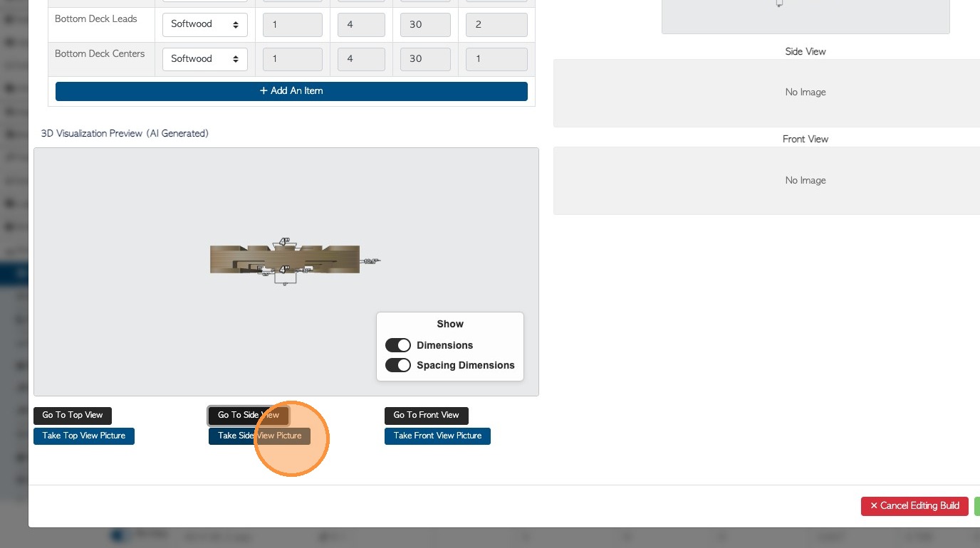
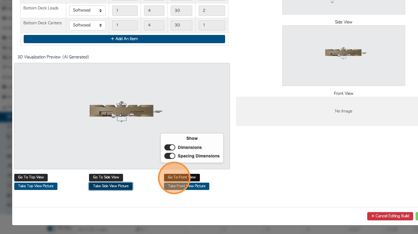
33. Click "Take Side View Picture" to add the side image.
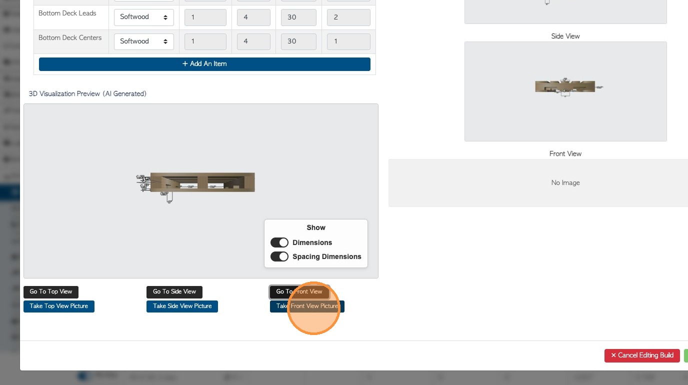
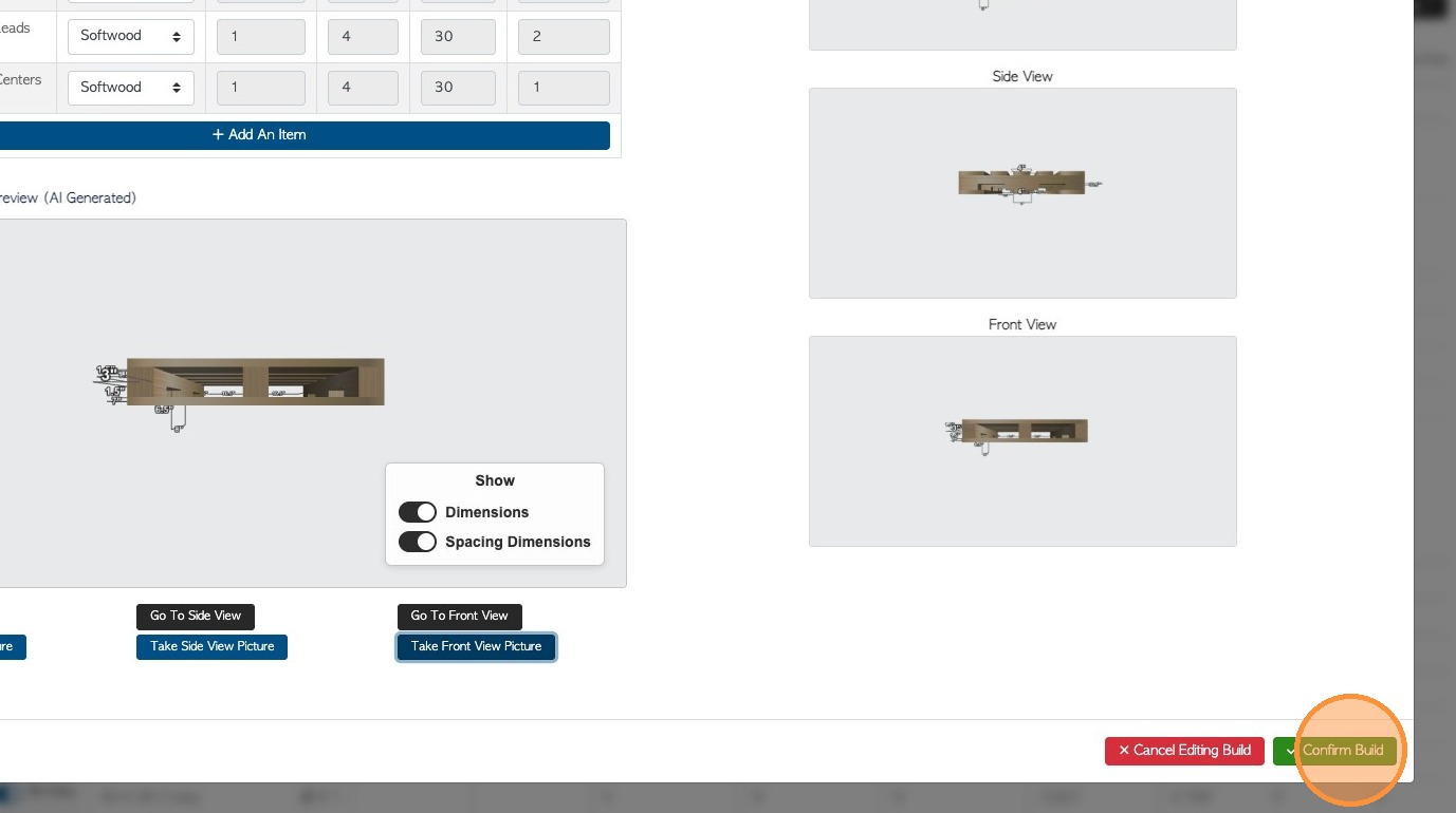
34. Finally click "Go To Front View"
35. Click "Take Front View Picture" to add the front view image.
36. Click "Confirm Build" to save all changes.
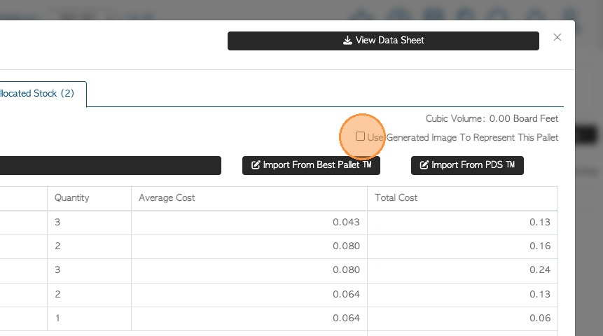
37. Click "Edit Build"
38. Click the "Use Generated Image To Represent This Pallet" field. The images will display in the stock item profile.
39. The image is available in Pallet Connect in the same places as the regular generated image e.g. orders, production pack etc.